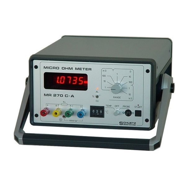
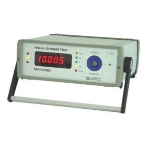
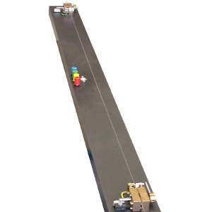
The MR270C-A is specially designed for electric resistance measurements in cable industry applications and inductive loads (transformers, motors). It is perfectly fit both for measuring the meter resistance in connection with a corresponding resistance measurement holding device or for final acceptance control of power cable reels. In the case of cable reels, which often have a cable length of several kilometers, both the compensation of the inductive component and the ability to perform measurements in the presence of high noise levels are important. This also applies to the winding resistance of transformers and motors
The highest accuracy is reached when meter sections are measured under water in order to obtain the highest possible temperature stability. The MR270C-A is designed for use with our resistance measurement holding devices, in particular since all connections of the 4-pole measurement are checked by the instrument. Wrong measurements are excluded. Owing to its high resolution the measuring error is very low, even with larger cable sizes. Cable reels are inductive, in particular if the reel itself is made of iron, and the cable length is very high. This “inductance” is very sensitive to interferences of any kind. Even a fork lift mtruck passing by generates a considerable interference voltage mduring the measurement by entering the magnetic field of the reel. To avoid error measurements, the MR270C can be set to a measuring method which guarantees absolutely stable measuring results even in such a case. To avoid error measurements, the MR270C can be set to a measuring
method which guarantees absolutely stable measuring results even in such a case.
For the measurement of winding Features resistances of motors and transformers it is important to use as high a measuring current as possible, so that the magnetic circuit, the iron, comes close to saturation, which is necessary to obtain stable results, in particular in the case of power transformers. At the same time the measuring instrument must “wait” until the measuring current flows uniformly and stable measuring results are obtained. The measuring time is therefore extended automatically until a stable measuring situation is obtained. For heat-up measurements, a regression calculation to t = 0 °C can be provided, which uses several measuring results at a constant time interval.
| Resistance measurement | |
| Range | 1 mΩ– 10 kΩ, decadic |
| Overrange | +80%, bis 18000 |
| Max. measurement error | ± 0,02% from MV ± 2 digits |
| Current | 10 A (at 1 mΩ) |
| Range selection | using keypad, via RS232 |
| Display | LED, 4 ½ digits |
| Speed | approx. 1 s to 6 s per measurement |
| Error detection prior to EVERY single measurement | |
| Current connection errors | display: ‚CUR‘, RS232: ‚ECUR‘ |
| Sense connection errors | display: ‚SEN‘, RS232: ‚ESEN‘ |
| Overrange >80% | display: ‚OVL‘, RS232: ‚EOVL‘ |
| Start of measurement | using keypad |
| via RS232 or IEEE - 488 | |
| via potential free contact | |
| via foot switch (optional) | |
| Ports | RS232C |
| printer (optional) | |
| start contact (potential free) | |
| IEEE – 488 (optional) | |
| Dimensions | 260 x 150 x 320 mm (WxHxD) |
| Weight | approx. 7,5 kg |

- Measuring range from 1 mΩ – 10 kΩ,
decadic - Overrange up to 80 %
- max. resolution of 100 nΩ
- Display LED, 4 ½ digits
- Measuring error ± 0,02 % of MV ± 2 digit
- Selectabe temperature compenstaion by probe or manual temperature input mit Sonde oder manuellem Wert
- Contact error detection prior to every single measurement
- RS232C port to control the instrument externally
DIN EN ISO 9001:2008


