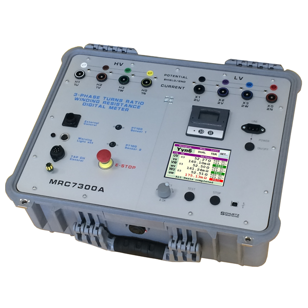
MRC7300A
Three Phase Transformer Measuring Bridge
for Resistance- and Ratio-Measurements
With the precision measuring bridge MRC7300A it is possible to safely determine winding resistances, transformation ratios and phase angles of distribution transformers up to 100MVA and more. Further it is possible to automatically move the tap charger of the H.V. winding to the next tap and perform cool-down measurements in temperature rise tests to calculate the resistance in the case of a load disconnection @ t0.
The MRC7300A 3-phase measuring bridge can be used by transfomer manufacturers, electricity supply companies and repair companies having to carry out on-site measurements under unfavourable conditions.
Resistance values ranging from 50 µΩ to 500 µΩ can easily be measured and logged with the internal measuring current of a maximum of 15 A up to a power of apprx. 100 MVA and more. To allow a compariosn of the measured values to previous measurements a conversion of the temperature of the test object is provided in order to compare measurements of a detached transformer carried out in the winter and measurements carried out in another season.
The provided Kelvin clips and lugs as well as all cables required allow an easy and safe connection of the measuring bridge to the test object. The tap changer can be moved and measured step by step by means of the automatic system which is connected to the tap changer’s signalling control of the transformer.
The measuring range is between 0.9:1 and 2500:1 in the case of the transformation ratio; the resolution of the angle measurment is 0.1 degrees. The logging of all measured values is performed by a seperate printer, computer or via the internal memory.
The magnetic loading of the transformer is performed quickly to a relatively high tsrating voltage (50V).
The unloading of the core is very safe, as the energy is destroyed in the MRC7300A by a ballast resistor and varistors except for a neglible rest.
Surge arresters protect the MRC7300A from peak voltages. During the moving of the tap changer to the next tap, with the measuring current still flowing, the measuring circuits are disconnected from the test object to protect the input amplifiers.
| Resistance Measurement | |
| Range | 50 µΩ - 500 Ω autoranging |
| Test object limits | about 30 to 250 MVA depends on type |
| Max. error | ±0.1 % of MV ± digit |
| Measuring Current, max. | 25 A |
| Loading Voltage, max. | 50 V |
| Measuring Power, max. | 250 VA |
| Ratio measurement | |
| Range | 0.900 - 2,500 autoranging |
| Max. error | ±01. % of actual value ± 1 digit |
| Measuring voltage | 180 V (other voltage on demand) |
| Measuring frequency | 50 Hz / 60 Hz (line dependent) |
| Phase angle measurement | |
| Range (one phase) | - 9.9 ° to + 9.9 ° |
| Range (three phase) | - 179.9 ° to + 180 ° |
| Max. error | ± 0.1 ° ± 3 digits |
| Magnetising current measurement | |
| Range | 1 MA - 2000 mA |
| Max. error | ± 1 % |
| Temperature measurement | |
| Range | - 20 °C to + 100 °C, linearized (for PT 100) |
| Max. error | 0.2 °K (without probe error) |
| Type of sensor | PT 100 temperature probe |
| Application | #1: Temperature for TC-Compensation #2: Temperature other test point optional more probes with internal or external scanner (depends on number) |
| Start of measurement | by using keypad and via USB |
| Interface | USB Thermo Printer |
| Size/Weight | H22 B42 T43 cm / approx. 16 kg |

- Automatic measurement without any manual interaction
- Resistance measurment with high accuracy and up to 15 A current
- Ratio measurement including phase angle and magnetising current
- Dual measuring method for faster measurements
- Automatic vector group detection
- Tap changer control measures all transformers taps automatically
- Heat-up measurement including algorithm for resistance at t=0
- Temperature measurement and compensation to 20 °C for Cu or AI
- USB port to get full external control over the instrument
- Thermo printer
DIN EN ISO 9001:2008


